Category Archives: Energy

Spider Silk Continues to Inspire Biotech Advancement


From folklore to children’s stories, it seems humans have always been fasterrificcinated with spider silk, the diverse material produced in abundance, at will from the body of nearly all species of spider. Studying the biomechanics of the spinnerets and the chemicals that combine to produce various textures of silk at a molecular level has allowed scientists a new perspective on efficiency and biosynthesis.

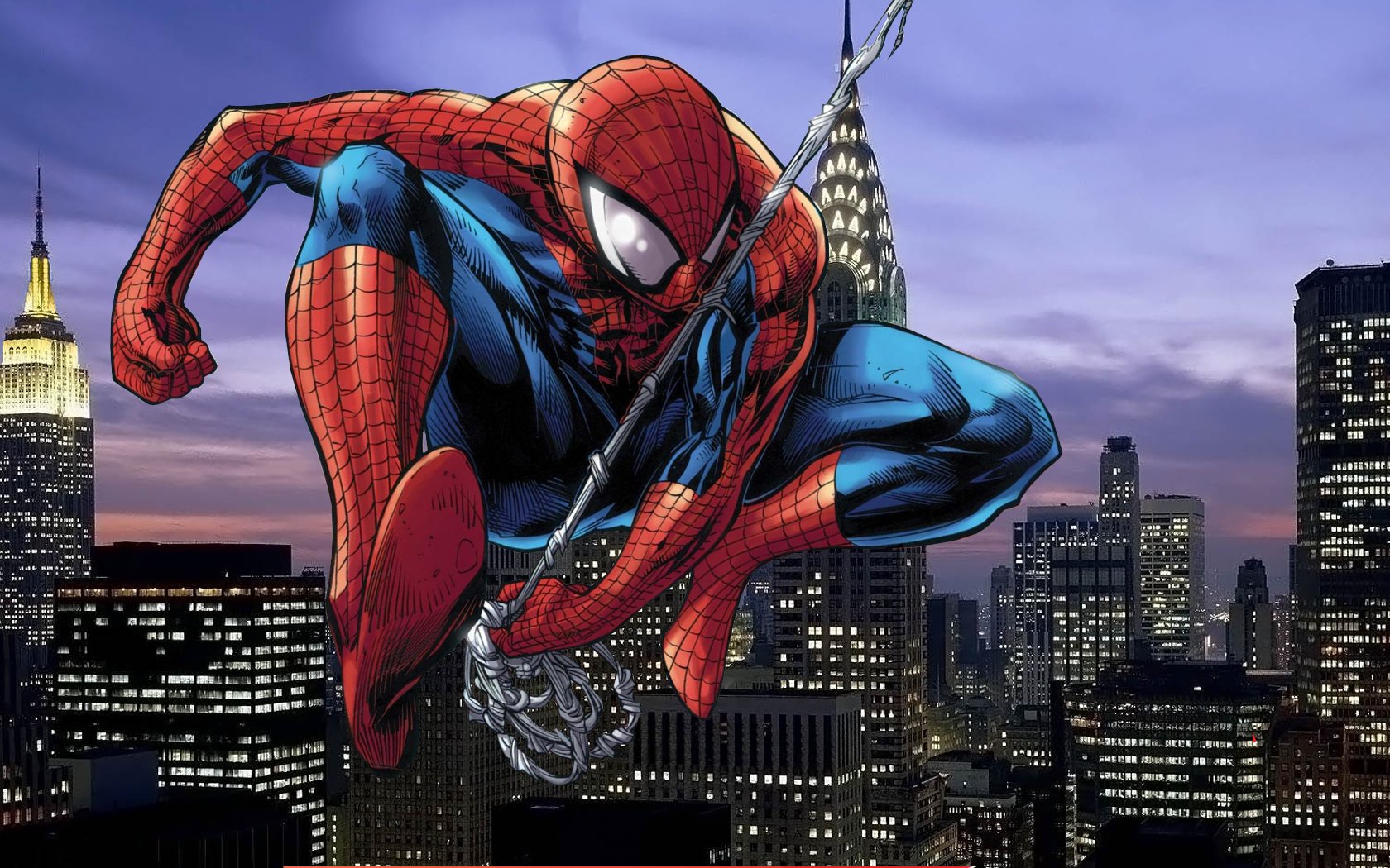
The golden orb-weaver spider (Nephila clavipes) produces so much silk everyday it has become the most studied spider in the world, and was even included in a trip to the International Space Station in a special terrarium. Golden Orb-Weaver silk is 30 times thinner than your average human hair. If Spider-man were to produce a proportionate thickness of the same material the line would likely hold, maybe even hold the weight of two adult humans(Valigra, 1999.)

Spider-manIt’s hard to find a material as strong while still retaining the flexibility and elasticity of spider silk. Maybe impossible. The dragline of the average spider silk is five times more durable than the Kevlar used in bullet-proof vests(Benyus, 2002, p. 132), plus, it’s lighter and breathes better. Kevlar is a petroleum product and requires pressurized vats of intensely hot sulfuric acid (Benyus, 2002, p.135; 2001). Biologically-inspired materials might be drastically more efficient on energy costs to create. Oil-based synthetic molecules often create dangerous bi-products which are hazardous to handle, expensive to store and virtually impossible to dispose. Spiders create superior materials with a very small amount of energy, heat or byproducts. (Benyus, 2001). NASA studies found that Gold Orb Spider spinneret systems can be so efficient they include reusing spider silk eaten and ingested after use.

silk

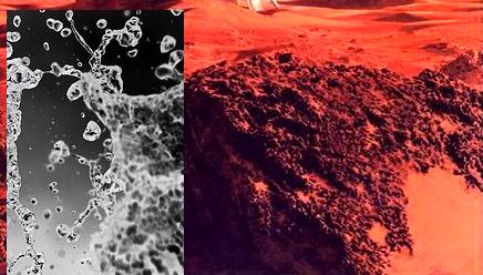
Electron-microscope imaging shows the variety of textures a single spider can produce from its body.

Spider silk would be so incredibly useful it might not even be possible to anticipate the range of products it might inspire. Most materials knows to man are either elastic or have a high tensile strength but some  pider silks fall in a  rare category of scoring high in both areas (Benyus, 2001). Spider silk can stretch 40 percent longer than its relaxed state without losing any of it’s shape when it returns. Even the stretchiest nylon can’t perform that way (Benyus, 2002, p.132; 2001). Dupont materials compared silk to current steel cables used on bridges and standing structures worldwide and found dragline spider silk strong enough to be used as the quick-stop brake system on a jet in flight on an aircraft carrier (Valigra, 1999), at a fourth of the thickness of steel cables.

“spider silk is so strong and resilient that on the human scale, a web resembling a fishing net could catch a passenger plane in flight. If you test our strongest steel wire against comparable diameter silk they would have a similar breaking point. But if confronted with multiple pressures, such as gale-force winds, the silk can stretch as well; something steel cannot do” (Benyus, 2001, 2002).

Spiders evolved the ability to spin a web strong and versatile enough to  allow it to run across, pull and twist into position and manipulate with its many legs in order to trap prey, set complicated tricks into action and run along without becoming entangled. The elasticity and strength of the web are partly why it is so easy for another species to become ensnared. Researchers who have taken the time to examine closely have realized in awe the potential for application in spaceflight, industrial, commercial and even fashion industries.

Spider silk also shows incredible tolerance for colder temperatures without becoming brittle or falling apart. Spiders are able to hide underground or near the warm trunk of a tree and return to their outdoor webs later to repair and rebuild what is largely left intact. These cold-tolerant properties lend superior promise to its potential as aan advanced suitable for bridge cables, as well as lightweight parachute lines for outdoor climbing in military and camping equipment. Scientists have been hyping up its many bumberpotential medical applications such as  sutures and replacement ligaments (Benyus, 2001) and as a durable substance to fabricate clothing and shoes (made of “natural fibers”) and synthetic moldable solid material that can create rust-free panels and hyper durable car bumpers. (Lipkin, R., 1996).

“if we want to manufacture something that’s at least as good as spider silk, we have to duplicate the processing regime that spiders use” Christopher Viney, early biomimetic proponent (Benyus, 2002, pp. 135-6).

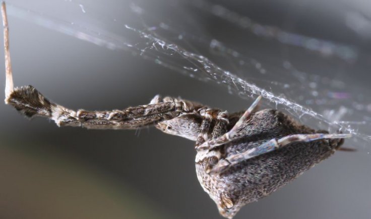
Take a look at the fascinating process as a spider creates silk and you will find something that more closely resembles human technology than animal biology. Spiders have evolved to create something highly specialized without tools or any sort of special diet requirements to fuel autosynthesis of silk.  Spider silk is formed out of liquid proteins within the spider’s abdomen. Several complex chemicals in a cocktail travel through the duct of a narrow gland. The substance is squeezed out in a very controlled manner through any combination of six nozzles called spinnerets. the protein collected from eating insects and various vegetable matters “emerges an insoluble, nearly waterproof, highly ordered fiber” (Benyus 2001).

Most spiders can produce a few different types of of silks. They can make threads that can be used to build structures, a strong dragline, or an elastic cable for repelling and reusing while creating the foundation for a web.  They can make a sticky, wet line that clings to itself and most other surfaces for fastening strong structures, making cocoons and trapping prey. There is much to be learned because all of human scientific knowledge on the subject still comes from a handful of studies of only fifteen or more spiders to date. There are 40,000 spider species, most of which we know almost nothing about. There might be even better silk from some species.

“But yes there is probably a tougher, stronger, stiffer fiber being produced right this minute by a spider we know nothing about. A spider whose habitat may be going up in smoke” Viney (Benyus, 2002, pp.138-40).

Jonathan Howard
Jonathan is a freelance writer living in Brooklyn, NY

Tech Can Make Oil Rail Shipping Safer


The Energy Information Administration recently released a map that reflects a massive change to our economy few people appreciate.

The graphic, shown below, shows the latest data on crude oil-by-rail movements around the country and the surge in oil shipments from North Dakota to the different corners of the country. Last year, trains transported more than one million barrels of oil per day in 2014 – a huge jump from 55,000 barrels per day in 2010.


Energy Information Administration

This increase in oil-by-rail transportation has come with a number of high-profile derailments, including an accident in Illinois just last month, which have caused substantial economic and environmental damage. Can technology improve safety? Yes. In much the way automobiles are becoming increasingly high-tech, various stakeholders in rail transportation are exploring various technologies to improve safety.

Building a better rail car (and maintaining it)

Railroads have already taken some steps to improve equipment with better braking systems and upgrades to the track infrastructure. New practices can improve safety as well, including better track inspections, speed restrictions for oil trains and choosing routes to reduce exposure to population centers. Railroads have also increased the use of freight car defect detectors installed alongside the the tracks that automatically identify mechanical defects on the railcars based on force, temperature, sound, or visual measurements.

The industry standard needs to be improved, say safety officials, but it’s unclear who will pay for upgrades.
Roy Luck, CC BY

Many of these technologies are already being implemented by the railroads both to improve safety and to increase economic benefits. In addition to minimizing the safety risk associated with derailments, improved track and vehicle inspection practices help to reduce the potential for delays, which can cost railroads hundreds of dollars per hour.

An economic analysis from 2011 estimated that the annual train delay costs due to railcar defects (resulting in trains stopping unexpectedly enroute) was over US$15 million for all US Class I railroads. For comparison, each year the four largest US Class I railroads spend an average of $35 million on track and equipment damages due to main-line derailments. Thus, the economic drivers behind the reduction of derailments and train delays are quite substantial.

Federal agencies and lawmakers are also working to ensure that federal safety requirements and public policy address the new transportation landscape resulting from the domestic oil boom and increased imports from Canada. The federal government is currently considering new safety standards for improved tank cars specifically designed for the transportation of crude oil.

However, movement towards such legislation has presented considerable challenges due to the fact that the vast majority of tank cars are owned by private companies other than the railroads that transport them.

As a result, questions arise regarding who should bear the economic burden of replacing and/or retrofitting the crude oil tank car fleet. Due to safety and economic incentives mentioned above, some railroads have already begun to purchase their own improved tank cars, but this has not become a universal trend across the industry.

Role of research

Researchers, too, are exploring how technology can improve safety in a variety of ways, including:

Improved Tank Car Design: The Association of American Railroads (AAR) is working to promote tougher federal standards for tank cars carrying crude oil and other hazardous liquids. Extensive research is ongoing both within the Federal Railroad Administration and at various universities to assess tank car safety and develop an optimized tank car design: Cooperative Research in Tank Car Safety Design.

Acoustic bearing detectors, the white-colored machines on either side of the tracks, take sound measurements which allow railroads to predict when railcar roller bearings are beginning to wear out.
Bryan Schlake, Author provided

Track and Infrastructure Inspection: Railroad track failures have been found to be a leading derailment cause in the US. As a result, railroads have begun to perform more track inspections, including the use of advanced track geometry vehicles – which use laser systems to measure the profile of the rail – on routes carrying crude oil trains. Ultrasonic rail inspection methods as well as ground-penetrating radar systems are also being developed to improve the ability of railroads to detect track defects.

Risk Assessment: Railroad transportation risk research associated with hazardous materials is ongoing. Risk assessment has included rail defect inspection, evaluating routing and train speed, track quality and an integrated framework to reduce risk. This framework addresses operating practices, train routing, infrastructure, and car design to identify the financial and safety risk associated with hazardous materials transport by rail.

Automated Condition Monitoring Technologies: Various wayside detector systems have been developed and installed across the country at locations adjacent to track to assess the condition of locomotive and freight car components enroute. These systems incorporate various technologies to identify critical defects resulting in both safety and economic benefits. Some key technologies include:

  • infrared temperature sensors used to measure overheated wheels/bearings

  • accoustic bearing detectors to identify worn roller bearings in railcars

    High-tech rail: a closer look at an acoustic bearing detector.
    Bryan Schlake, Author provided

  • laser systems to measure wheel profiles and identify worn wheels

  • machine vision systems to detect low air-hoses, structural defects and broken or missing railcar safety appliances

  • load impact sensors to identify damaged wheels that are out-of-round or exhibit flat spots.

Advanced Braking Systems: Both technology and operating practices can play a role in improving braking for oil trains. Some have suggested the use of Electronically Controlled Pneumatic (ECP) brakes. ECP brakes allow for faster application of the brakes on all cars in a train using an electric signal, instead of an air signal, to initiate a brake application.

ECP brakes have been used on a limited basis for coal trains, but the costs have not been proven to justify the safety and economic benefits. A better option may be the use of either:

  1. distributed power, where locomotives are dispersed throughout the train (i.e. front, rear and even in the center) and/or

  2. two-way end-of-train devices (EOTD) that allow brake signals to be initiated from the rear of the train.

Both of these operating practices result in faster braking and reduce “run-in”, where the cars in the front of the train begin braking before those on the rear, causing the rear cars to “run-into” the cars in front of them, creating higher in-train forces. After these measures were proposed by the US Department of Transportation in July of 2014, US Class I railroads agreed to implement enhanced braking in the form of distributed power or two-way EOTDs on all oil trains.

A derailment in Lynchburg, Virginia in 2014 emptied at least one car’s load of crude into the James River
Waterkeeper Alliance Inc., CC BY-NC-ND

Positive Train Control (PTC): This technology will automatically slow or stop a train to prevent a collision or derailment due to human error, such as speeding or missing a signal. After a federal mandate in 2008, railroads have begun to develop and install this GPS-based safety overlay system, which will eventually cover more than 60,000 miles of track in the US.

Emergency Response: Railroads are working together with various organizations to improve community safety through emergency response training.

Reducing risk

In addition, new technologies are being developed to improve the speed and effectiveness of environmental cleanup efforts. For example, researchers at Penn State University have developed a patented technology called Petro-SAP to absorb oil from the environment after a spill. Technologies like this can be used in the future to mitigate environmental impact of train related oil spills.

While the risk associated with oil train derailments has not been eliminated, the transportation of crude oil by rail has certainly become safer through extensive research, development and implementation of new technologies.

Continued efforts by railroads, government agencies, research institutions and universities will continue to improve the safety of crude oil transportation by rail, reducing risk and potentially alleviating public fears associated with railroad transportation.

For more on transporting oil by rail, see: Despite disasters, oil-by-rail transport is getting safer.

The Conversation

This article was originally published on The Conversation.
Read the original article.

Recent News for Earth
X
  • How the Moon Was Formed
  • PEEK UNDERGROUND WHEN A MISSILE OR METEOR STRIKES EARTH


    In a demented kind of way, when either a missile or a meteor strikes Earth, as much havoc as it can cause, it is pretty exciting. While the destruction it can cause above ground is fairly apparent, there is a whole three-ring circus going on underground that is a bit more difficult to see. But physicists at Duke University have come up with special techniques that have fitted them with the means to simulate high-speed impacts in artificial soil and sand, and observe the underground ramifications in slower-than-slow motion.

    One discovery that they have come up with via their lab experiments is that upon such forceful impact, soil and sand indeed become stronger the harder they are struck. This unearthing serves to explain why efforts to force ground-penetrating missiles deeper underground by just shooting at them more quickly and with greater impact don’t really pan out. In reality, projectiles come against resistance to a greater extent and will actually stop before their strike speed has a chance to reach full throttle.

    THE EXPERIMENT

    In order to replicate the occurrence of a missile or meteor thrashing into soil or sand, the scientists plummeted a metal projectile with an orb-shaped tip from 7 feet above into a pit of beads. Upon impact, the kinetic energy of the projectile was taken on by the beads and dissipated as the beads bumped into one another below the surface, absorbing the energy and force of the collision.

    To visualize this force as it moved away from the point of the crash, the researchers employed beads that were made of clear plastic which transmit light differently when compacted. When observed through polarizing filters such as those found in regular sunglasses, the portions of greatest stress showed up as branching chains of light referred to as “force chains” that move from one bead to the next during the impact, akin to lightening bolts that zig-zag their way across the sky.

    The metal projectile plunged into the vat of beads at a speed of 6 meters/second, or close to 15 MPH. Via the use of beads of varying hardness, the researchers made it possible to trigger pulses that rippled through the beads at speeds ranging from 67 to 670 MPH. At low speeds, a small number of beads carried the brunt of the force, and at higher speeds the “force chains” grew more extensive, resulting in the energy of the crash to move away from the point of the collision a lot more quickly than predicted by previous models. New contacts are generated between the beads at higher rates of acceleration as they are pressed together, and that is the cause for strengthening the material.

    TO SUM IT UP

    Said co-author Abram Clark, currently a postdoctoral researcher in mechanical engineering at Yale University:

    “Imagine you’re trying to push your way through a crowded room…If you try to run and push your way through the room faster than the people can rearrange to get out of the way, you’re going to end up applying a lot of pressure [to] and ramming into a lot of angry people!”

    Mars isn’t a One Way Trip Anymore


    150 Cubic Meters of Ice Means a powerful rocket fuel can be synthesized on Mars – powerful enough to escape Mars gravity for the return trip to Earth.

    Turns out Mars has 150 billion cubic-meters worth of ice that’s been frozen for so long it’s covered with Mars’ ubiquitous red soil. NASA knows this because of  radar measurements from the Mars Reconnaissance Orbiter. The ice is spread out among a few ginormous belts made of countless glaciers.

    There’s been evidence of a once liquid ocean on Mars’ surface.  Curiosity rover found riverbeds back in September 2012 with NASA able to estimate two pints of water for every cubic-foot of soil. In early 2014, Spanish researchers were able to prove glaciers dug canyons 3.7 billion years ago. Water leaves chemical byproducts of various reactions and residues.

    No one expected such a big find, except maybe anyone who saw the Arnold Schwarzenegger version of Total Recall.

    If you are wondering where Total Recall got the idea for underground glaciers, scientists  have suspected glacial activity below the Martian surface for decades. The debate centered around formations that would not be abel to hodl their particular shape without glacial activity but was the frozen material water ice, dry ice, or a muddy mix of red dust and water or some other frozen gas or liquid.


    Using logic and science, the evidence available can now be interpreted to be enough to cover Mars with a meter of liquid water, if it melted – and if Mars was completely smooth.

    Glaciers of Mars Image: Mars Digital Image Model, NASA/Nanna Karlsson


    “We have looked at radar measurements spanning ten years back in time to see how thick the ice is and how it behaves. A glacier is after all a big chunk of ice and it flows and gets a form that tells us something about how soft it is. We then compared this with how glaciers on Earth behave and from that we have been able to make models for the ice flow.”

    Read Nanna Bjørnholt Karlsson entire press release on the subject.

    Water can easily be separated into hydrogen gas and oxygen, making breathable air and a powerful rocket fuel that can be used for other space missions, including a return trip to Earth. Water can also be used to cultivate food and animal crops on Mars, making colonization a hell of a lot more appealing.

    Oh, and one more thing:

    Jonathan Howard
    Jonathan is a freelance writer living in Brooklyn, NY

    Why ocean energy needs a cyberinfrastructure to thrive


    Almost one third of our electricity needs can be met by a predictable, renewable and yet largely untapped resource: ocean waves.

    Generated by wind blowing over ocean waters, ocean waves travel large distances with little loss of energy. As such, they are a renewable resource that is more consistent and predictable than wind or solar generation.

    Our research team at Lehigh University is examining how to design, operate and maintain future wave energy farms by using digital technologies to integrate them smoothly to the electric grid.

    Wave farms contain arrays of wave energy converters (WECs), devices that convert the energy in rolling ocean waves to electricity. Smart wave farms also include energy storage such as batteries, sensors, communications capabilities, computational resources, and electronics to deliver electricity to an on-shore grid connection point.

    All these components, as well as the algorithms that control them, together describe the cyber-physical infrastructure of the wave farm. Our team, which has people with a background in everything from wireless data communications to fluid dynamics, is determining how to optimally deploy and operate this infrastructure.

    We are exploiting the predictability of ocean waves to aid people who operate wave farms and to optimize farm production. We are also deeply interested in the sustainability and market potential for future wave farms. Unlike other renewables that require fossil-fuel based generation to balance out their variations, consistent wave power will have lower CO2 emissions. We are evaluating this effect and are studying what profits wave power producers can expect in the electricity market.

    Predictable and renewable

    Estimates of economically recoverable wave energy along the US coasts range up to 1,170 terawatt-hours (Twh) per year using existing technology.

    Total electricity consumption in the US is approximately 4,000 TWh/year and coastal states use nearly 80% of the nation’s electricity. This means that the potential for clean, renewable wave power production in the US is very high.

    Ocean wave characteristics can be reliably predicted up to 48 hours in advance and waves are available 90% of the day on average, compared to 20-30% for wind and solar. This key benefit will provide wave power producers more lucrative market opportunities than are currently available to more variable renewables. These profits could also offset the high initial costs of installing wave farms.

    PowerBuoy from Ocean Power Technologies captures energy from waves.
    Ocean Power Technologies

    As an emerging industry, wave energy conversion faces other challenges. For example, more testing infrastructure is needed. But to do that, current regulatory and permitting procedures have to be updated for this technology. And the environmental impact of withdrawing large amounts of wave energy must be studied further.

    Over the past two decades, several types of WEC devices have been developed and deployed. There have been commercial-scale wave farms deployed in Australia and Europe, but none has been put online in the US.

    For ocean energy to scale up, we will need to fill some gaps in our knowledge. In the future, wave farms will not be a collection of individual generators. Instead, they will be a complex cyber-physical system and require interdisciplinary tools.

    Complex interactions

    We are interested in the wave farm as a system, and in its interactions with the ocean environment, the power grid, and the electricity market. We are exploring the predictability of waves using both in-ocean sensors as well as forecasting algorithms. The predictions can be used to adapt the WECs energy capture, or energy storage decisions.

    In our project, we are working on wave farm systems that blend tools from hydrodynamics as well as communications and computing. We will use sensors and controllers to predict power, optimize output and integrate with electricity markets. We will validate the economic and environmental feasibility of wave power and use our research and development to realize the potential of wave energy conversion at large scale.

    WECs in a farm will also interact with each other. Besides absorbing power from incoming waves, individual WECs reflect waves which will mix with incoming waves and impact how much energy can be captured at neighboring WECs, and vice versa. These interactions must be understood and accounted for in controlling the farm’s total output. This total power produced will in turn impact grid integration, emissions, and market interactions.

    How a wireless researcher began studying the ocean

    Our project team is comprised of researchers from a wide variety of backgrounds: fluid dynamics, signal processing, operations research, economics and wireless communications, which is my own background. So how does a wireless communication researcher end up working on wave energy farms? The answer is in the following picture:

    An artist’s rendition of a wave farm with several Ocean Power Technologies’ PowerBuoy wave energy converters. Image is used with permission from Ocean Power Technologies.

    The buoys are WECs collecting energy from undulating sea waves. To me, they resemble wireless antennas receiving sinusoidally varying electromagnetic signals. In both cases the buoys/antennas are placed in a field of waves to capture energy. The statistical variations of wireless radio signals and ocean waves are similarly captured.

    Significant performance gains in modern wireless communication systems have come from using multiple antenna systems. For wave energy to be successful at the grid-scale, we will also require multiple buoys, or wave farms.

    There are solid connections between a wave farm and a communication system scenario I have studied extensively in the past. Making these initial connections got my foot in the door and I have been making similar connections since.

    Desalination?

    Besides powering the electricity grid, wave farms could also be used in powering a variety of off-shore applications. Our project team is interested in developing wave farm designs tailored for such energy needs. For example, we are interested in developing smaller scale wave farms that address the energy requirements for off-shore water desalination processes.

    In many parts of the world, groundwater is shrinking but sea water is prevalent. The presence of sea water may also imply availability of local wave energy resources that can feed water desalination systems. We are interested in developing cyber-physical infrastructure for such autonomous wave farms. The solutions may push forward water desalination technologies that could in turn help address the global water crisis.

    The Conversation

    This article was originally published on The Conversation.
    Read the original article.

    Can water from coal seam gas be re-injected into the ground?


    One of the major concerns about coal seam gas (CSG) extraction is what to do with the water produced in the process, as well as more general concerns about the industry’s impacts on groundwater. But what if the water produced by CSG extraction could be recycled and returned to the ground?

    My new research, carried out as part of CSIRO’s Gas Industry Social and Environmental Research Alliance, shows that it is possible to re-inject this CSG-produced water into aquifers, and that water quality issues should be insignificant as along as the situation is carefully monitored.

    Why re-use the water from coal seam gas?

    In Queensland, the state government’s policy on managing “produced water”, also commonly known as “CSG water”, is to “encourage the beneficial use of CSG water in a way that protects the environment and maximises its productive use as a valuable resource”.

    The government’s policy says that CSG water should, where possible, be used to benefit one or more of the following: the environment, existing or new water users, and existing or new water-dependent industries.

    If that is not possible, and once feasible beneficial uses have been considered, the regulations say that CSG water should be treated and disposed of in a way that avoids or minimises environmental damage.

    CSG produced water has several possible uses, depending on its quality, quantity and level of treatment, including:

    • supplying local farmers and communities;

    • irrigation of agricultural crops or plantation forestry;

    • dust suppression;

    • industrial purposes such as drilling, coal washing, power station cooling;

    • replenishing weirs and dams, or restoring flows in rivers exposed to heavy irrigation demand;

    • recharging aquifers.

    CSG companies in Queensland are therefore testing the viability and potential environmental impacts of re-injecting treated CSG produced water. This first involves treating the water to remove dissolved salts and other chemicals, after which the water quality is often better than in the target aquifers for re-injection.

    A critical question is what will happen to the quantity and quality of the groundwater already in the receiving aquifer. This is the question we have tried to answer, by building on existing computer models to develop a method of predicting the local and regional impacts on water quality and quantity.

    We built and integrated four models that simulate groundwater flow and how any contaminants might travel through aquifers. One of the models used was based on the regional groundwater model developed by Queensland’s Office of Groundwater Impact Assessment to study groundwater flows through the Surat Basin.

    The other three, finer-scale models were built to better understand the groundwater system and impacts of re-injecting treated CSG water at varying distances from the injection well. Some of the key questions we tried to answer using these models were:

    • If the water quality in the aquifer changes, how far and how long would it take for the re-injected water to dilute back to the background water quality?

    • Are there any domestic or stock bores at risk of contamination?

    • How does the possible presence of geological faults influence the predictions?

    The results

    The model simulations of large scale re-injection of treated CSG water into the Precipice Sandstone in Surat Basin showed that an increase in groundwater pressure would occur on a regional scale. The groundwater level could increase up to a maximum of 140 m in the observation bores near the re-injection site. But the maximum increase in groundwater level in stock and domestic wells, which are located far from the re-injection site, are expected to be minimal.

    For example, the nearest domestic and stock bore is around 15 km from the re-injection well site, and simulations show that the maximum groundwater level increase in this bore would be 4.3 m (some of the bores in this region are free-flowing artesian bores, meaning that water already reaches the surface under pressure from below).

    This increase can occur naturally even without any re-injection, and so may not necessarily be a risk. Also, the increase in groundwater level means that availability of fresh water in this region is increased and can be drawn out over many decades. The model also illustrated that changes in groundwater levels in other aquifers overlying the Precipice sandstone would be minimal (see below).

    Diagram of the groundwater system in the Surat Basin.
    Office of Groundwater Impact Assessment, Author provided

    We also used our models to identify potential changes in groundwater quality. The results showed that re-injected treated CSG water would be diluted to very low concentrations (1% or less of the original concentration) within 5 km of the injection well.

    There were no domestic and stock bores located within 5 km of the injection well, this means the risk of contamination of such bores located in the Precipice Sandstone from re-injecting treated CSG water is considered insignificant.

    However, given the proposed injection wells are spread over a large area and the uncertainty of mobilising contaminants already present in the formation, it will be essential to monitor continually the groundwater quality, to detect and contain any undesirable changes.

    This article was co-written with Catherine Moore, Senior Groundwater Modeller, GNS Science, New Zealand.

    The Conversation

    This article was originally published on The Conversation.
    Read the original article.

    Why rooftop solar is disruptive to utilities – and the grid


    A report earlier this month detailed how electric utilities were working through state regulators to stunt the spread of rooftop solar, the latest tactic in a campaign an industry group started three years ago.

    What worries utilities so much? At one level, the problem is obvious: customers with rooftop solar panels buy less energy and pay less to utilities. But the issue is not limited to giant utility companies’ earnings potential. After all, we all use electricity and rely on utilities to maintain the power infrastructure.

    Why is solar so threatening to utilities? And how is the rapid growth of solar changing how the grid works? The answers lie in the sometimes-arcane world of electric utilities and their business model. In all the change, though, there needs to be a discussion over how solar fits into the grid and how to ensure grid reliability.

    Disruptive

    Power-generating panels, called solar photovoltaics (PV), represent the fastest-growing source of electric power in the United States. In percentage terms, installed PV has grown four-fold over the past several years, and costs have fallen as rapidly as installations have risen.

    The point of so-called “grid parity,” where the cost of generating electricity from solar PV falls to the point of being competitive with conventional power generation sources such as coal or natural gas, appears to be fast approaching. In some states, most notably Hawai’i, it has probably already arrived.

    Large-scale solar power plants will continue to get built. But it is in the many millions of rooftops (and in the future, building facades) where the real potential for solar energy as a disruptive technology is taking shape. By installing solar panels, a consumer pays the utility less and, for the first time, becomes an energy producer rather than a consumer only.

    As more solar comes online, demand on centralized power plants declines, making it harder to maintain reliability of service.
    Nikolaj F. Rasmussen, CC BY-NC

    Electric utilities in many states have responded in ways that, on the surface, conjure up stereotypical images of big companies trying to crush small competitors. Utilities have asked their state regulators to assess high fees on homeowners that install solar PV panels but maintain their connection to the electric grid. An Arizona utility, for instance, proposed levying a monthly US$50 grid interconnection fee for consumers with solar PV.

    Net metering rules – which allow homeowners to sell surplus electricity from their solar panels back to the grid – are being challenged as well. Utilities are seeking additional restrictions on net metering or to reduce the price they pay homeowners for this surplus power.

    Monopolies behaving badly?

    The loss of revenue from solar PV is primarily happening in sunny states such as California and Arizona but also in less-sunny New Jersey and others states with generous solar incentive programs.

    But what happens when utilities – which, after all, are in the business of selling electricity – continue to lose business? The more kilowatt-hours generated by rooftop solar panels, the fewer kilowatt-hours sold by utilities. With fewer kilowatt-hours sold, utilities have a harder time justifying investments in new power stations, transformers and other types of capital investments that utilities earn money from.

    How to pay for upkeep? We all rely on the grid and, ultimately, utility customers pay for it.
    miuenski miuenski, CC BY-NC

    While it makes economists cringe, the use of the political system to disadvantage competitors is hardly a novel business strategy. Yet the response of some utilities to the rapid growth in rooftop solar cannot, however, be so simply portrayed as incumbents guarding their turf at all costs.

    Electric utilities have a unique role in society and the economy, one that is rooted in a set of arrangements with state regulators that goes back nearly a century. In exchange for being granted a geographic monopoly on the distribution of electric power, the utility is responsible for ensuring that its transmission and distribution systems operate reliably. In other words, it is the utility’s responsibility to ensure that blackouts occur infrequently and with short duration.

    Regulators, meanwhile, need to allow the utility to recover the costs associated with maintaining the grid infrastructure and ensuring reliability. So ultimately, the costs of building and maintaining a reliable system fall, for the most part, on utilities and their ratepayers.

    Infamous duck curve

    At first blush, the rise in rooftop solar installations would seem like a boon for reliability – after all, solar panels can be installed so that peak solar PV production is roughly correlated with the hours of peak electricity demand. The more power that is taken off the grid and placed onto solar panels, it would seem, the lower the blackout risk is.

    There is some truth to this. In fact, electric system operators have been paying customers to take demand off the grid for many years during times when the grid is stressed.

    But because the boom in rooftop solar PV is not controlled by utilities, there are some genuine implications for the cost of keeping the rest of the grid operating reliably. With enough rooftop solar, the daily patterns of power supply and demand change dramatically.

    This famous graph, called the duck curve, shows how rooftop solar panels are supplying so much power during the day that the demand on central power generators is falling dramatically.
    California ISO

    One of the best-known analyses of this change and its potential costs is known as the “duck curve” from the California Independent System Operator (see figure, above). A typical day’s electricity demand in California has historically featured two peaks – one in the morning and a larger one in the afternoon. There’s a trough, or “shoulder,” period between them. Fleets of different power plants are fired up to meet this pattern of daily electricity demand and to match the ramp-up and ramp-down.

    Now that California has substantial solar on its grid, the daily demand curve is starting to look very different. With solar panels cranking out power during the midday hours, the overall demand for power from the grid – that is, from central power plants – during the shoulder period in the middle of the day declines substantially. Solar PV energy production could grow so much that by 2020 the demand for grid-provided electricity would be lower at 12:00 noon than at 12:00 midnight. The two peak periods form the head and tail of the duck; this dip in the middle of the day forms the belly of the duck.

    Cord cutting from the grid

    Normally, lowering the demand for electricity would be good for society. Costs would decline and stress on the grid would decrease. But the deep dip in grid demand during the middle of the day – the duck’s belly – has significant implications for the costs of keeping the grid operational.

    It is not the case necessarily that fewer power plants would be needed. Instead, different power plants would be needed – ones that could rapidly adjust output to offset the rise in solar PV production. The solution may well involve a mix of power plants and other strategies to control demand during certain hours. California has recently set up an entirely new market for this so-called “ramping” capability, and the costs will eventually trickle down to ratepayers in the state.

    The second implication for the cost of maintaining reliability will seem familiar to anyone who has thought about the telephone company. The rise of “cord cutters” – people with a cell phone but no land-line – places land-line phone companies in a quandary. They must continue to maintain their network infrastructure with fewer customers to pay for it.

    Electric utilities are not quite there yet, but the day could well be coming. Unused power plants could be retired, but electric transmission lines, substations and other delivery infrastructure generally cannot simply be declared unused and retired because that infrastructure is collectively needed for reliability. Ratepayers typically support this infrastructure through the several cents paid for every kilowatt-hour they consume.

    Homeowners that install solar PV are, in most places, shifting the cost of this infrastructure to ratepayers that have not installed solar panels. There is thus the potential to create a type of “death spiral.” The more homeowners that install rooftop solar, the more expensive the grid maintenance costs become for everyone else, which in turn encourages more homeowners to install solar panels to avoid higher utility costs.

    In the near term, states with high penetration of rooftop solar may need to restructure how the grid is paid for. This technology will eventually force a conversation about the fundamental role of the electric utility and who should have ultimate responsibility for providing reliable electricity, if anyone. Going off the grid has a certain appeal to an increasing segment of the population, but it is far from clear that such a distributed system can deliver the same level of reliability at such a low cost.

    The Conversation

    This article was originally published on The Conversation.
    Read the original article.

    Tandem Solar Cell Provides High-efficiency, Low-cost solar


    Maximizing the efficiency of converting sunlight to electricity was the primary goal for much of the history of solar power industry. Because solar cells were so expensive to make, they were used only in special applications, such as on spacecraft, where performance was more important than cost. That game changed a couple decades ago with the advent of thin-film solar cells that forced the industry to focus on lower costs rather than high performance.

    Now that solar cells are less expensive to manufacture, the industry has entered a third phase with the goal: increasing efficiency while keeping low-cost manufacturing.

    Most commercial solar photovoltaic cells are made from silicon. To push the efficiency higher, one of the best options is to make tandem solar cells – that is, cells that use multiple light-absorbing materials. For perspective, silicon solar cells have a record efficiency of 25.6%. Using one light-absorbing material, the theoretical limit is 34% efficiency. Using two light-absorbing materials in tandem pushes the theoretical limit to 46% efficiency.

    My colleagues and I made tandem solar cells from two light-absorbing materials: silicon and the metal-halide perovskite, a new material with the potential to be manufactured at low cost. In a paper published this week, we showed how these two materials can be connected in a single solar cell and a way to harvest the power in a novel way.

    These developments lay the foundation for silicon-perovskite tandem solar cells and may provide a path forward for the solar industry to make high-efficiency, low-cost solar cells.

    Capturing more of the light

    One way to reduce the cost of solar is to improve the efficiency of the solar panels. With a higher efficiency, fewer panels, or modules, need to be installed to reach a desired power target. This means less labor, less land and less hardware.

    To understand why a tandem cell offers a boost in efficiency, one has to look at how different solar cell materials react to incoming light.

    Sunlight contains visible light and wavelengths of light that can be converted into electricity.
    MIT OpenCourseWare, CC BY

    Sunlight is made up of a wide variety of energies, from ultraviolet light and visible light, which have a higher level of energy, to infrared light, which is lower energy. A solar cell uses a semiconducting material like silicon to absorb the sun’s light and convert it to electrical power. A semiconductor has a special property called a bandgap that allows it to both absorb light and extract the energy from the light as electricity.

    Most solar panels have a single absorbing material, such as silicon. There is a tradeoff when choosing the bandgap of the absorbing material. With a smaller bandgap, a wider range of energy from the sun can be absorbed, generating more current. However, a smaller bandgap also means a smaller voltage at which the electrical current can be extracted. Because electrical power is voltage multiplied by current, there is a sweet spot. Too small of a bandgap and the solar cell produces a large current but small voltage and the opposite for too large of a bandgap.

    Tandems minimize this tradeoff. When using two absorbers, each absorber specializes in a portion of the solar spectrum rather than a single absorber responsible for the entire solar spectrum. The first absorber is responsible for all visible and ultraviolet particles of light, or photons. Underneath it, the second absorber is responsible for the infrared photons. Having these specialized absorbers minimizes the loss of energy that occurs when sunlight is lost as heat, rather than electric current.

    We use the metal-halide perovskite as the first absorber in our tandem to capture the ultraviolet and visible light and silicon as the second absorber to capture the infrared light.

    Metal-halide perovskite: specialized absorber

    A popular new photovoltaic material is the metal-halide perovskite. The word “perovskite” actually describes the crystalline structure of any material made of three components in a ratio of 1:1:3. The metal-halide perovskite used for photovoltaics is one part metal (commonly lead), three parts halide (commonly iodine), and one part organic molecule (commonly a molecule called methylammonium). When lead, iodine and methylammonium are combined into a perovskite crystal structure, a semiconducting material is formed.

    Perovskite is a class of materials that hold promise for inexpensive solar cells.
    Rob Lavinsky, iRocks.com, CC BY-SA

    The metal halide perovskite is a rare and exciting material. It works well as a solar cell and specializes in absorbing ultraviolet and visible photons. For a number of reasons, very few materials work well as solar cells and very few of these solar cell materials specialize in this portion of the solar spectrum. This is a major reason that tandem solar cells haven’t been widely used.

    It can be formed entirely using processes similar to printing newspapers. The perovskite is dissolved as a solution similar to an ink and is printed onto a glass or silicon substrate, as a newspaper is printed on paper. These processes are very inexpensive. What is perhaps most surprising is that the solar cell works well when made in this fashion. Most solar cell technologies that work well require expensive or specialized processes and tools.

    Prototyping tandems

    In our experiments, we developed two layers unique to a tandem solar cell that aren’t used in conventional silicon solar cells. We made an electrically connecting layer called a tunnel junction out of silicon that connects the two light-absorbing materials together.

    We also made a transparent electrode, which conducts electricity while also letting light pass through it, to connect the solar cell to external wires so that power can be extracted. We made this transparent electrode out of a mesh of silver nanowires, which is similar to a chain link fence made of wires one thousand times thinner than the width of a human hair. With those layers, we can begin to design the other layers in a multi-layered solar cell.

    The design of the light-absorbing materials in a tandem is significantly different from standard solar cells. While there is much work to be done, these tandem solar cells made from silicon and metal-halide perovskite hold substantial promise for continuing the evolution of the solar industry.

    The Conversation

    This article was originally published on The Conversation.
    Read the original article.

    Eiffel Tower Goes Green


    An ambitious remodel project at the Eiffel Tower is making its operations greener. The first floor of the landmark building was recently refurbished for a better visitor experience and to improve the environmental impact of the historic building. First floor glazing was changed to provide a 25% reduction in solar heat gain during the summer months.… Continue reading